
1996 · BODY [42] · страница 14 из 16 · Открыть оригинал PDF ↗
Текст распознан со скана. Числа и обозначения можно сверить с оригиналом ниже.
INSPECTION AT KEYLESSeNTrY RECEIVER ECU TERMINALS
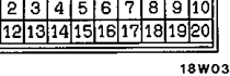
(1)Remove the combination meter: [Refer to BASIC MANUAL (Looseleaf edition) GROUP 54 - Combination
Meter:]
(2) Disconnect the amplifier and inspect the connector onthewire harness side as shown in the chart
below:
Таблица в оригинале

Распознанный текст таблицы — требует сверки с оригиналом
| Terminal | Signal name | Conditions | Terminal voltage | |
|---|---|---|---|---|
| Door switch | Room lamp switch: OFF or ON | One or more doors are open (Door switch: ON) | 0 V | |
| All doors are closed (Door switch: OFF) | 0 V | |||
| Room lamp switch: DOOR | One or more doors are open (Door switch: ON) | 0 V | ||
| All doors are closed (Door switch; OFF) | System voltage | |||
| Door lock actuator switch (driver's side) | LOCK | 5 V and pulse output | ||
| UNLOCK | 0 V | |||
| Key remainder switch | ke OFF (When ignition | y is inserted) | 5 V and pulse output* | |
| ignition key ON When | is removed) | 0 V | ||
| Ignition switch | Ignition switch: ACC o | r ON | System voltage | |
| Ignition switch: OFF | 0 V | |||
| 10 | Receiver power supply | At all times | System voltage | |
| 11 | Room lamp output | All doors are closed | Room lamp switch: OFF or ON | 0 V |
| (Door switch: OFF) | Room lamp switch: DOOR | System voltage | ||
| 12 | Door lock output | During door lock contr LOCK | ol unit output, or door lock switch: | 0 V |
| Other than above | System voltage | |||
| 14 | Door unlock output | During door lock contr or door lock key cylin | or door lock switch ol unit output, der: UNLOCK | 0 V |
| Other than above | System voltage | |||
| 20 | Earth | At all times | 0 V |
NOTE
Values marked withshould be measured using an oscilloscope. (The value will alternate between 0 V and 0.03
V if & circuit tester is used )
Оригинальная страница руководства
