
MANUALS · INTAKE AND EXHAUST [15] · страница 14 из 30 · Открыть оригинал PDF ↗
Текст распознан со скана. Числа и обозначения можно сверить с оригиналом ниже.

SERVICE POINTS OF INSTALLATION
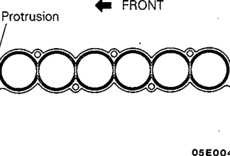
31. INSTALLATION OF INTAKE MANIFOLD GASKET
Install the gasketsSOthattheprojections faceinthe
directions shown in the illustration_
30. INSTALLATION OF INTAKE MANIFOLD29. CONE DISC SPRING
Tighten the intake manifold mounting nuts one bank after
the other by the following procedure.
sFor green cone disc spring?
(1) Tighten the nuts in the right bank to 7 Nm (0.7 kgm, 5
ft.Ibs )
(2) Tighten the nuts in the left bank to 20 to 23 Nm (2.0 to
2.3 kgm, 14t0 17 ft Ibs )
(3) Tighten the nuts in the right bank to 20 to 23 Nm (2.0 to
2.3 kgm; 14 to 17 ft Ibs )
(4) Repeat steps (2) and (3) one moretimerespectively:
<For black cone disc spring>
(1) Tighten the nuts in the right bank to 3 to 5 Nm (0.3
to 0.5 kgm, 2.2 to 3.6 ft.Ibs ) .
(2) Tighten the nuts in the left bank to 12 to 15 Nm (1.2
to 1.5 kgm,9 to 11 ftlbs ).
(3) Tightenthenuts inthe rightbank to 12 to15Nm
(1.2 to 1.5 kgm; 9 to 11ft.Ibs ).
(4) Repeat steps (2) and (3) one more time respectively
23. INSTALLATION OF HIGH-PRESSURE FUEL HOSE
(1) Apply a little amount of new engine oil to the O-ring:
Caution
Besure to prevent the engineoil from entering
into the delivery pipe:
(2) Insert the hose, being careful not to damage the0
ring, and tighten securely
21. INSTALLATION OF AIR INTAKE PLENUM GASKET
Mitsubishi Motors Corporation
Install with gasket protrusions in the position illustrated.
Оригинальная страница руководства
