
MANUALS · EMISSION CONTROL [17] · страница 40 из 46 · Открыть оригинал PDF ↗
Текст распознан со скана. Числа и обозначения можно сверить с оригиналом ниже.
GLOW AND EGR CONTROL UNIT <SUPER QUICK GLOW SYSTEM>

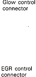
TERMINAL VOLTAGE MEASUREMENT
NOTE
(1) Inspect with the glow & EGR control unit connectors still
connected,
When measuring the voltage, the earth will be the glow
& EGR unit terminal no. 30.
Terminal Voltage Reference Table
Таблица в оригинале

Распознанный текст таблицы — требует сверки с оригиналом
| Glow & EGR control unit inspection terminal | Inspection item | Inspection conditions | Standard value |
|---|---|---|---|
| Ignition switch: OFF 7 ON | 11 - 13V | ||
| EGR solenoid valve No.1 | idling While engine is after having warmed up, suddenly race the engine | Momentarily increases | |
| Throttle lever idle position Ignition | 0.3 -1.5V | ||
| Lever position sensor | switch: Throttle lever fully open OFF ON position | 3.7-4.9V | |
| Sensor power supply <MT only> | Ignition switch: OFF ON | 5.5V 4.5 | |
| Ignition switch: OFF ON | 11 _ 13V | ||
| EGR solenoid valve No.2 | While engine is idling after having warmed up, suddenly race the engine_ | Momentarily decreases |

HARNESS CONTINUITY INSPECTION
Disconnect the glow & EGR control unit connector
(2)Check to be sure that there is continuity (1.31.9 kO) be-
tweentheharness-side connector terminals 10 - 11_
Оригинальная страница руководства
