
MANUALS · REAR AXLE [27] · страница 28 из 50 · Открыть оригинал PDF ↗
Текст распознан со скана. Числа и обозначения можно сверить с оригиналом ниже.
SERVICE POINTS OF REMOVAL
EZ7QBAI
5REMOVAL OF REAR AXLE SHAFT ASSEMBLY
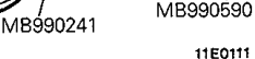
Pull out the right and left axle shafts by about 70 mm (3
in:). If it is difficult topullout, use the special tools:
6_REMOVAL OF REAR PROPELLER SHAFT
Make the mating marks on the flange yoke of the rear
propeller shaft and the companion flange of the differen-
tial case.
9REMOVAL OF DIFFERENTIAL CARRIER
Remove the attaching nuts ad strike the lower part of
differentialcarrierassemblywithpieceoftimber
several times to loosen, then remove the assembly:
Caution
Donotremovetheuppermostnut but keep
loosened all the way to the stud bolt end
2Use care not to strike the companion flange.
SERVICE POINTS OF INSTALLATIONE27QBAK
6.INSTALLATION OF REAR PROPELLER SHAFT
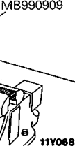
Align the mating marks on the flange yoke and the com-
panion flange to install the rear propeller shaft.
INSPECTION BEFORE DISASSEMBLYEZ7QDAA
Hold the special tool invice, and install the differential car-
rier to the special tool.
FINAL DRIVE GEAR BACKLASH
With the drivve pinion locked in place, measure the final drive
gear backlash with a dial indicator on the drive gear_
NOTE
Measure at four points or more on the circumference of the
drive gear
Mitsubishi Motors CorporationDec1993
Standard value:<No. 6 differential>
0.11-0.16 mm (0.0043-0.0063 in.)
<No.7 differential and No. 7.5 differen-
tial (except rear differential lock)>
0.13-0.18 mm (0.0051-0.0071 in )
<No.7.5differential(reardifferential
lock)>
0.12-0.18 mm (0.0047-0.0071 in.)
PWJE9086 EREVISED
Оригинальная страница руководства
