
Pajero II Workshop Manual 1991 · FUEL · страница 69 из 339 · Открыть оригинал PDF ↗
Текст распознан со скана. Числа и обозначения можно сверить с оригиналом ниже.
TROUBLESHOOTING HINTS
Hint 1:
If thenumber steppermotor steps increases to
100-120 steps or decreases to 0 step, the cause
maybe presumedtobemalfunctionofthe
Ordamaged or disconnected wiring
stepper moto
of the harness_
Hint 2:
Ifthenumberof steppermotorstepsdeviates
fromthe standard value even through the results
of the checking of the harness of the idle-speed
control servo and of the component itself indicate
noabnormalcondition,thecausemaybe
presumed to be one of the following
(1) Improperadjustmentofthestandardidling
speed.
(21Depossits adhered to the throttle valve_
(31 Leakage of air into the intake manifold from
gasket gap, etc.
(4) Incompletecombustionwithinthecylinder_
(Malfunctionofthespark plugs,the ignition
coil,the injectors, the compressionpressure
etc )
Проверка
Using Multi-use tester (MUT)
Таблица в оригинале

Распознанный текст таблицы — требует сверки с оригиналом
| Function | Item No_ | Data display | Check conditions | Load conditions | Standard value STP |
|---|---|---|---|---|---|
| Data reading | 45 | Stepper motor steps | Engine coolant temperature: 85-958C (185-2059F) ih d i | Air conditioner switch: OFF | 2-12 |
| Lgts an accessores: OFF Transmission: neutral (P range for vehicles with AVT) | 'Air conditioner switch: ON | 30-70 | |||
| Steering wheel: neutral position idle-position switch: ON (The compressor clutch should be actived when the air conditioner switch switched ON ) Engine: idling | Air conditioner switch: ON Selector lever: shift to range | 20-60 |
NOTE
When the vehicle is new [driven approximately 500 km (300 miles) or less] the number of steps may
be about 30 steps greater than the standard value indicated above
Caution
Whentheselect leveris shiftedto the"D"range, thebrakesmustbeusedto prevent the
vehicle from moving forward
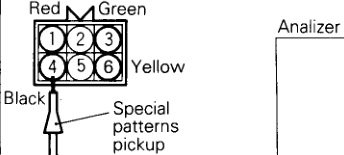
Wave Pattern Inspection Using an Analyzer Observation method
(1)Disconnectthe steppermotorconnector,andconnect
the special tool (test harness: MB998463) in between:
(2) Connect the analyzer special patterns pickup to the step
per motor-side connector terminal(red clip on the spe-
cial tool) , terminal(green clip) , terminal(black clip)
and terminal 0 (yellow clip) respectively

Оригинальная страница руководства
