
MANUALS · FUEL [13] · страница 44 из 340 · Открыть оригинал PDF ↗
Текст распознан со скана. Числа и обозначения можно сверить с оригиналом ниже.
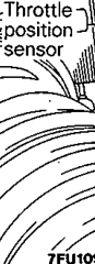
(2) Measure resistancebetweenterminal(sensor earth)
and terminal 0 (sensor power)
Standard value:3.5-6.5 kQ2
(3) Connecta pointer typeohmmeterbetween terminal
(sensor earth) and terminal @ (sensor output}
(4) Operate the throttle valve slowly from the idle position to
the full open position and check that the resistance chan-
ges smoothly in proportion with the throttle valve open-
ing angle_

(5) If the resistance is out of specificationor 'fails to 'change
smoothly, replace the throttle position sensor
TPS installation torque:2.0 Nm (0.2 kgm, 1.5 ftIbs)
For the idle position switch ad throttle position sensor
adjusting procedure, refer to P.13-17.
IDLE POSITION SWITCH

OPERATION
The idle-position switch functions to convert (to
HIGHILOW-level voltage) data as to whether the
accelerator is depressed or released, and to input
that voltage (as signals) to the engine control unit:
Theengine control unit, based upon those signals,
regulates the idle-speed control servo.
Voltage withinthe enginecontrol unit is ap-
plied, byway ofthe resistance,tothe idle-
positionswitch:Whenthe : foot istaken off
theaccelerator,theidle-positionswitchis
switchedON,so thecurrent isearthed.As
result;the idle-positionswitchterminalvolt-
age changes from HIGH to LOW level.
Оригинальная страница руководства
