
MANUALS · FUEL [13] · страница 140 из 340 · Открыть оригинал PDF ↗
Текст распознан со скана. Числа и обозначения можно сверить с оригиналом ниже.
SENSOR INSPECTION

(1) With the accelerator pedal released, check to be sure that
the throttle valve lever or the fixed SAS is pushed,
NOTE
If it is not pushed, adjust the fixed SAS (Refer to P.13-79-
23,)
(2) Disconnect the throttle position sensor connector.
(3) Check the continuity across the throttle positionsensor
connector terminal(Sensor earth) and(Idle position
switch)
Таблица в оригинале
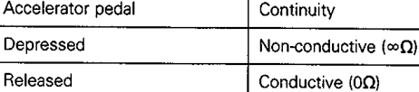
Распознанный текст таблицы — требует сверки с оригиналом
| Accelerator pedal | Continuity |
|---|---|
| Depressed | Non-conductive (6Q) |
| Released | Conductive (0Q) |
NOTE
If there is no continuity when the accelerator pedal is returned,
loosen the throttle-position sensor installation screw; then
after turning all the way in the clockwise direction, check
again.
(4) Replacethe throttle-position sensor (idle-position switch
incorporated) if there isa malfunction.
NOTE
For the idle position switch and throttle position sensor
adjusting procedure, refer to P13-79-22
Оригинальная страница руководства
